Showing posts with label Arcade. Show all posts

Wednesday, 22 January 2014

Kung Fu Master - Repair Log

Kung Fu Master - Repair Log

I've had this one in my to-do pile for many months now, the pcb belongs to a fellow member of the Jamma+ site; Beaps.

I felt really bad for having this one in the shop for so long, but after many dead-ends I'd finally made some progress.

The middle board originally seemed to have several intermittent soldering failures - cracked joints, burnt pins (from previous repairs perhaps?) and a few scratched traces - and the on-screen faults would come and go if the boards were tapped or flexed.


First off, I bypassed the burned pads with jumper wires..


And likewise the cut traces..


(Taped the wires down once the job was complete)


Thought that would be the end of it.. but what was previously an intermittent glitch had became a rather permanent problem.  The more I worked on the board, the worse it seemed to get (..and hence returned to the pile many times, for months). :/

But last night I recognised the visual glitch as being similar to a problem I encountered while working on an unrelated FPGA project..


So the instinct led me to the bus multiplexers.. the: 74LS157 chips.

Swapped the first one out..


Like so..


But now the fault was more solid than before - not fixed, but stable - were on the right track I guess..

Looking around the board I found four more 74LS157's, and with the trusty ninja-finger technique..
if the pins of two of them were touched (without applying pressure), the pattern on the screen changed from, this:


To this:


To me this indicates floating-pins, or dead memory cells (depending on the chip at hand).
And sure enough, all the 157's were Fugitsu's - which are known to have their gold wires detach from the silicon over time.. (this is well documented in many repair logs)

This ether detaches a pin completely & makes it 'floating' (neither 0 or 1) - or (as with this board initially) would produce an intermittent fault - even though the pcb looks good - it will be affected by vibration / prodding.

So went round with a logic probe & mapped out the state of all the pins while it was running..
(z = tri-state)


It turned out 3 more 74LS157 chips were pretty Fek'ed..


Next, I piggy-backed some new chips on the back of the old & on powering up the pcb, the display was restored!! \o/ Yay!

Unfortunatly.. murphy's law struck!

While de-soldering the three ic's several pads & the connected tracks came away with the iron!

The heat wasn't even set that high!! Argh!! Ruined!! Noooooooooo..
(a proper Darth-Vader moment)


Gutted! a real deal breaker potentially, so to be thorough I mapped out where all the affected pads went to with a continuity tester & draw a diagram (you can't see the traces once you fit the chips back):


Decided to solder the three new chips straight into the PCB - because you can't solder the top side under a socket.

And patched her up with kynar wire:


Then by 2am.. *drum roll* ..... All in check!

Kung Fu Master was once again, restored to it's former glory.


And as they say...

Monday, 20 January 2014

Shinobi - Repair Log


Shinobi - Repair Log


Thanks to a supreme act of kindness of a very kind gentleman (who works next door) I am now in possession of an absolute classic..! (He also happens to run a rather good 8bit Sega preservation site)

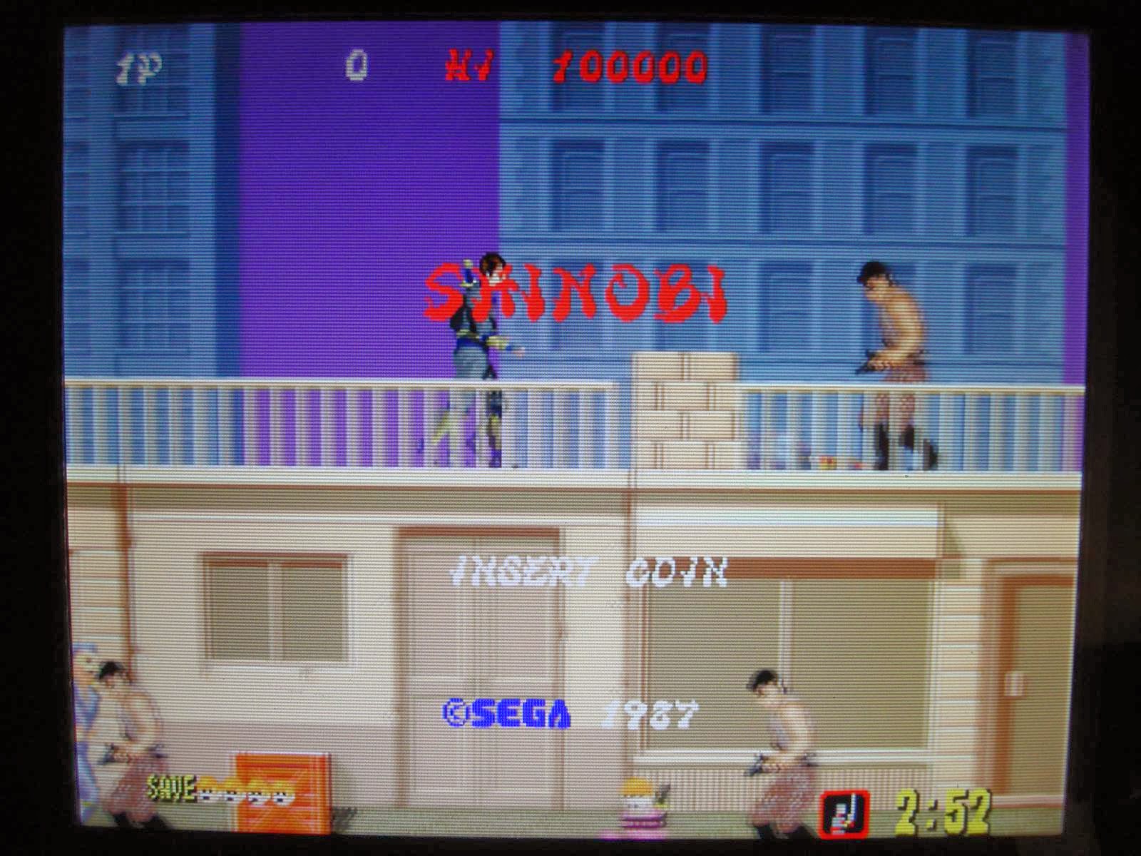
The seminal 1986-'87 Sega p.c.b. Shinobi \o/ 


Much <3 for this game! Thanks again dude, insanely kind of you ..I'll get her working again.

In fact, I actually managed to on the same night I recieved the board. :D 
(eager would have been an understatement)

First port of call: several physically broken capacitors on the top ROM board:
  
 
Desoldered all four smoothing-caps from the top ROM board:


Found 220uf replacements in the parts box.. they are a little larger / high rated, but they will work nicely.


 Like so:
 
 
Still no luck though.. this wasn't enough to bring the board back to life..

So I next assumed the encryted CPU's battery had run dry, and lost it's memory..

 
So swapped out the CPU for a stock 68000 processor:
   

..burned a pair of replacement unencrypted program ROMs.

 
But still now picture! :'(

Probing the video output pins with the scope showed that the RGB was working, 
but the SYNC line was static.. nada! 

Following the trace from the SYNC pin, round the edge of the board lead to this tiny scratch.. 


Under the microscope.. It's a clean break, we have a winner.


I soldered over the break, but thought it a bit weak.. 

So fitted a thin green wire that bypasses the cracked trace.


Which ran from the Jamma connector:


Right across the pcb - to the other end of the cracked-trace:


And once the little power was applied....

\o/ Shinobi lives again :D


 An absolute classic game! Hard as nails of the highest difficulty setting!!


Hopefully this game will last another 26 years to come :)


Friday, 26 July 2013

Double Dragon - Repair Log - Day 3

Double Dragon - Repair Log - Day 3

Fixed the 1 & 2 player buttons I/O.. and all looks good for this one!

Though on my bartop i do get the occasional sync roll!?! :( .. I found the schematic to see where the sync pin leads to, but if goes off one page & must become Japanese on another. :/

I scoped the signals around the video connector and supply, and I get a god solid 5v power rail, RGB going from 0-1v and the sync line going from 0-2v .. Large 0 pulse (v blank) with finer 0-2v pulses in between (h blank).

I compared the signal with some other boards and it looks legit :D which suggests another theory..

Are the sync issues due to the CGA-VGA converters I'm using on my flat-panel?

Short answer.. Yes. The pcb was verified working by the owner on his CRT.

WARNING! (To anyone working on one of these boards!)

I had to re-fit the four board spacers back between the two boards before it was taken away..

Oh boy!!! :S

On double dragon there are two plastic spacers ... and two metal ones ...  
Yeeeeeeeah...

I placed them in a rather arbitrary arrangement, tightened the bolts & powered up.. 
Wait for it... F***in shite loads of smoke poured out of my Jamma loom!!!

Turns out that.. Well you know the big fat traces that run around the outside of the PCB'S? They're usually earth / ground / 0 volts, right?

Not this time! One surface of each board is 0v and the other is 5v. Two of the corner bolt holes are seperated buy a split in the PCB track (running round the edge) - two are not.

If you get the metal corners wrong then it's smoky time - so please be careful and make a note of where they came from when you take the boards apart!

I assume the metal rods actually carry the power and ground from the top to the bottom board (when in the right corners) & the 0 & 5v on each side of the board is acting as RFI suppression.

Luckily there was no real damage done.. The direct short through the metal board spacer rods protected the board.. I'm just gunna need some heavier cable for my 5v line. ;)

"A dragon with two metal teeth!"

Thursday, 4 July 2013

Double Dragon - Repair Log - Day 2

Double Dragon - Repair Log - Day 2

Okay.. I did something a little silly ..not in a baaaad way tho.

I've bought another broken Double Dragon board on fleaBay to assist in the repair.. (hope I wasn't bidding against Beaps!! :D) - cost £37 all-in - ruuning at a lose, but hey, at least I can keep the scraps.

It arrived last night & I immediately swapped the top board from the new one with Beaps rusted one (remember the resistor pack issue?):


As the one I received locks up on boot, I fitted Beaps brand-new processor & US Rom set:


And... drum-roll....


We have a good picture - all that remains now is the player 1&2 start buttons don't respond, booo.. :(

Bet £1900 some one had previously rear-ended the 12v line.. (reversed the Jamma connector)

There looks to be some previously attempted repairs around this region of the board, so I know where to look first..

Saturday, 22 June 2013

Double Dragon - Repair Log - Day 1

Double Dragon - Repair Log - Day 1

Today Beap's Double-Dragon board that came out to play..


Some repair work had previously been carried out on this board, and it looked like Ram & sound substitutions primarily.. The CPU had also been replaced.


But on power up there was an unnerving buzz for two seconds and blocks of corrupt data in a static pattern across the screen. :(

First I had to remove some rust from the sound side of the board..


And there was a region of the board where a 5-pin-resistor-pack had been previously removed..

Cleaned the rust & crusty flux & ordered some parts..

Will have to completely rebuild the tracks - this damage shouldn't stop the board from booting - but I won't expect the sound to function too well until it is resolved.


And from below:


Also removed a big metal pin that was shorting a transistor:


The soldering around the previous repairs didn't look too healty, lots of dry flux, a couple of shorted traces and maybe even a split track or two. :/


Cleaned it all up a bit.. reflowed the solder - removed all the shorts, and attempted a power test..

It' booted! - Not without issue though.. but its playing and makes a few sound effects on start-up!

Some progess at least.


The sprites & BG-layers looked to be functioning.. looks like the Font layer is glitched - will have to probe those Ram chips, to see if they have to be replaced.


To be continued...